Introduction
------------
First of all note that this pocket computer is for hobby use, it is not for industrial use.
Cobalt 3 has been designed to give everyone the opportunity to build their own computer in the easiest way possible. This allows you to have fun learning and building something that is complete and functional, within limits.
Assembling a computer is very complex even if it is supplied as a kit to assemble. For this reason I realised this project: to give everyone the opportunity to make a computer on their own. And to make it easier, this little computer is a sbc (single board computer). This means that all the necessary components are on a single electronic board.
Also included are a display and a keyboard, to avoid having to plug it into another computer to see what goes on the screen or to type commands.
A battery is also included in the card, so you can put Cobalt 3 in your pocket and carry it with you, when you go out or go to school or work.
Required Skills
---------------
Assembling. Although the list of components is kept to the minimum, there are about 200 soldering points, which means that you need some experience. I started from scratch, and I took other less complex kits to learn how to solder.
So you should be able to assemble beforehand that this step has been taken.
Tools
-----

You just need normal soldering tools as a soldering iron, a magnifying glass, and a third-hand tool for holding the board, etc
Here a link to an easy soldering tutorial for beginners:
Soldering Tutorial for Beginners: Five Easy Steps
Components
----------
Note that components and board images can be different in shape and color.

Try to visualize where the various components go on the board.
Then assemble the board in different steps.
I suggest to start with the smaller parts.
List:
1 × atmega328p
1 × Oled Display 128x64 SPI 7 pins
1 × AAA battery holder
1 × socket 28 pin narrow
1 × AAA Li-Ion battery 3.7v 350-600 mAh
1 × Crystal 16.000 MHz
1 × led
1 × 220 Ohm resistor
1 × 1 K Ohm resistor
1 × 33 K Ohm resistor
2 × 22pf capacitor
1 × 10⁴nf capacitor
1 × header 6 pin
1 × toggle switch 3 pin
40 × tactile momentary switches
This is how It will look at the end.

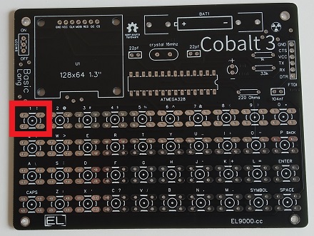
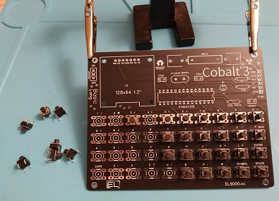
1) Tactile momentary switch

First insert and solder all 40 switches on the keyboard
2) Resistors and capacitors
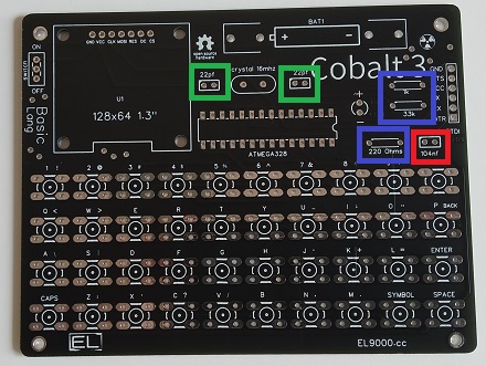
In the green rectangle 2 x capacitors 22pf
In the red one 1 x capacitor 104nf
In the blue one 3 x resistors, from the top to bottom:
- 1K Ohm resistor
- 33K Ohm resistor
- 220 Ohm resistor
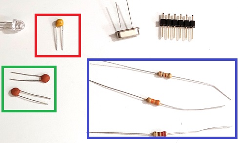
Put the resistors on the board in the same order.
Match the color of the rectangles.
3) Toggle switch, led, crystal and 6 pin header
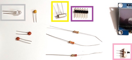
In the yellow rectangle 1 x Crystal 16.000 MHz
In the grey one 1 x led
In the purple one 1 x header 6 pin
In the pink one 1 x toggle switch
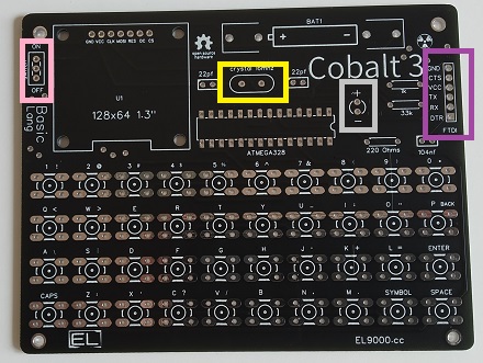
Match the color of the rectangles.
Pay attention to the legs of the led, the longer is the positive, the shorter the negative.
4) Microcontroller socket and battery holder

In the white rectangle 1 x battery holder
In the orange one 1 x socket
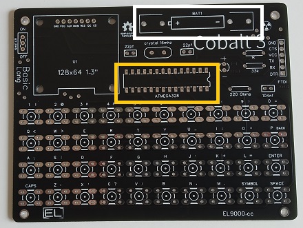
Pay attention to the right position of those components.
There is a notch on the socket and on the atmega328 that shows you what the right fitting is.
Fit correctly the positive and the negative side of the battery holder.
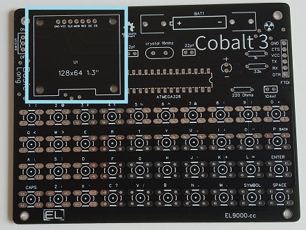
4) Oled display
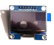
Fit it in the light blue color rectangle. Pins name can be different, don't worry about it, only the right position of the component is important.
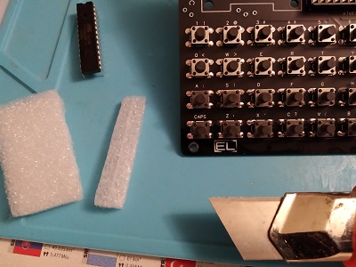
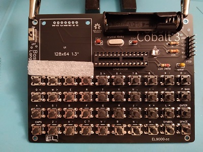
If you don't have like me any feet or spacers to use to space the display, I simply put something under the display while I solder it.
After soldering I remove it.
Finishing and Cleaning
----------------------
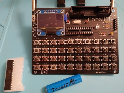
When you're done assembling, fit the microcontroller in the socket and then clean the board.
Cleaning the board is a good practice, I use Isopropyl alcohol because is highly efficient in dissolving most commonly found PCB contaminants, it's also electrically non-conducting and evaporates quickly.
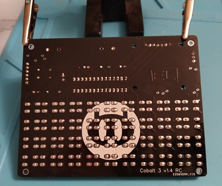
Dry, and turn off the switch. Then put on the battery and turn on the switch.
Using the tape
--------------
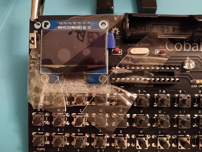
You also might want to know, how to hold the components on the board when soldering if they aren't still.
Personally, to fix the components on the pcb when soldering I use adhesive tape, but only if they tend to come off.

How to solve problems
---------------------
How to troubleshoot a circuit board? There's a nice video here:
Detecting pcb failures
The most important tool to find any problems is the multimeter, but in this case, given the simplicity of the circuit, any problem will generally boil down to the bad positiong of the components or to the badly made solder joints.
So do an accurate visual inspection, check that all the components are positioned correctly, and if they are, then use the magnifying glass to verify that the solder joints have been well made.
I used this guide, by Zakariah Martin-Taylor:
Soldering tips and tricks
Thanks for reading. Happy soldering!
Cheers,
Leonardo
You just need normal soldering tools as a soldering iron, a magnifying glass, and a third-hand tool for holding the board, etc Here a link to an easy soldering tutorial for beginners: Soldering Tutorial for Beginners: Five Easy Steps Components ---------- Note that components and board images can be different in shape and color.
Try to visualize where the various components go on the board. Then assemble the board in different steps. I suggest to start with the smaller parts. List: 1 × atmega328p 1 × Oled Display 128x64 SPI 7 pins 1 × AAA battery holder 1 × socket 28 pin narrow 1 × AAA Li-Ion battery 3.7v 350-600 mAh 1 × Crystal 16.000 MHz 1 × led 1 × 220 Ohm resistor 1 × 1 K Ohm resistor 1 × 33 K Ohm resistor 2 × 22pf capacitor 1 × 10⁴nf capacitor 1 × header 6 pin 1 × toggle switch 3 pin 40 × tactile momentary switches This is how It will look at the end.
1) Tactile momentary switch
First insert and solder all 40 switches on the keyboard

2) Resistors and capacitors In the green rectangle 2 x capacitors 22pf In the red one 1 x capacitor 104nf In the blue one 3 x resistors, from the top to bottom: - 1K Ohm resistor - 33K Ohm resistor - 220 Ohm resistor
Put the resistors on the board in the same order. Match the color of the rectangles.
3) Toggle switch, led, crystal and 6 pin header
In the yellow rectangle 1 x Crystal 16.000 MHz In the grey one 1 x led In the purple one 1 x header 6 pin In the pink one 1 x toggle switch
Match the color of the rectangles. Pay attention to the legs of the led, the longer is the positive, the shorter the negative. 4) Microcontroller socket and battery holder
In the white rectangle 1 x battery holder In the orange one 1 x socket
Pay attention to the right position of those components. There is a notch on the socket and on the atmega328 that shows you what the right fitting is. Fit correctly the positive and the negative side of the battery holder. 4) Oled display
Fit it in the light blue color rectangle. Pins name can be different, don't worry about it, only the right position of the component is important.
If you don't have like me any feet or spacers to use to space the display, I simply put something under the display while I solder it. After soldering I remove it.


Finishing and Cleaning ---------------------- When you're done assembling, fit the microcontroller in the socket and then clean the board. Cleaning the board is a good practice, I use Isopropyl alcohol because is highly efficient in dissolving most commonly found PCB contaminants, it's also electrically non-conducting and evaporates quickly.
Dry, and turn off the switch. Then put on the battery and turn on the switch. Using the tape -------------- You also might want to know, how to hold the components on the board when soldering if they aren't still. Personally, to fix the components on the pcb when soldering I use adhesive tape, but only if they tend to come off.
How to solve problems --------------------- How to troubleshoot a circuit board? There's a nice video here: Detecting pcb failures The most important tool to find any problems is the multimeter, but in this case, given the simplicity of the circuit, any problem will generally boil down to the bad positiong of the components or to the badly made solder joints. So do an accurate visual inspection, check that all the components are positioned correctly, and if they are, then use the magnifying glass to verify that the solder joints have been well made. I used this guide, by Zakariah Martin-Taylor: Soldering tips and tricks Thanks for reading. Happy soldering! Cheers, Leonardo